Anchors: Between a Rock and a Hard Place
Foundation Findings #05 - August 1989
Anchor testing is not an exact science.
Most experts agree, however, that the best way to determine an anchor's holding power is to set it in a natural seabed and exert a straight-line pull from a boat while measuring with a strain gauge the amount of force required to drag or break it out of the seabed. Over the years, a wide variety of anchor tests have been performed, often by anchor manufacturers, who rate their anchors according to holding power and use these ratings in advertisements and technical brochures. Most manufacturers publish conservative figures based on a series of tests. While their methodologies may be similar, their tests are conducted in a wide variety of seabeds-from loose sand to gooey mud-in a wide range of water depths, and using rode of various scope made up of varying proportions of chain and rope. There are so many variables at work here that results vary widely from one test to another. An anchor that has been proven to hold 3,000 lbs. In hard sand with a scope of 6:1 in one test, might hold only 350 lbs. In soft mud with a scope of 3:1 in another test. The lesson here is that it is futile to compare the holding strength of two anchors tested under different conditions. And even with objective, reliable data. Results from different tests measuring different performance criteria reveal how difficult it is to design and perform an unbiased anchor test.
ln January 1989, the BoatUS Foundation and Cruising World magazine jointly sponsored tensile strength tests of seven anchors. Unlike many other anchor tests, we were able to eliminate the bias of a manufacturer-sponsored test. Our collaboration with Cruising World brought another independent, objective participant into the testing. The testing procedure was carried out by engineering and technical experts in an independent testing laboratory, Com-Tex Development Corp., at the University of Lowell, Massachusetts.
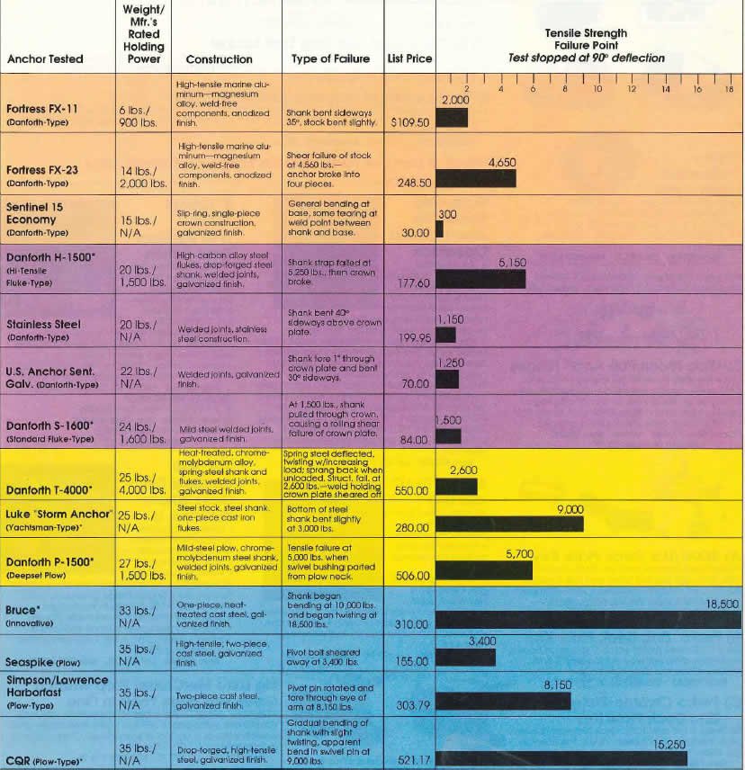
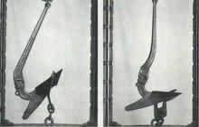
The test procedure was designed to simulate the type of load that results from an anchor's fluke(s) being lodged in rock, coral, a stump, or other unyielding surface in a strong wind or stressful retrieval situation. Specifically, we wished to compare the bending/breaking strength of the seven anchors listed in the table below, which are of similar size and weight and recommended for like-sized boats. All anchors were supplied off the shelf; their manufacturers were not aware that a test was being performed.
The Contenders
| Anchor Tested | Construction | Weight | Mfr.'s Rated Holding Power |
|---|---|---|---|
| Danforth S-1600 (standard fluke type) | Mild steel, welded joints, galvanized finish | 25 lbs | 1,600 lbs |
| Danforth T-4000 (Deepest Hi-tensile fluke-type) | Heat-treated, chrome-molybdenum-alloy, spring-steel shank and flukes, welded joints, galvanized finish | 25 lbs | 4,000 lbs |
| Danforth H-1500 (Hi-tensile fluke-type) | Hight-carbon alloy steel flukes, drop-forged steel shank, welded joints, galvanized finish | 20 lbs | 1,500 lbs |
| Danforth P-1500 (Deepest Plow) | Mid-steel plow, chrome-molybdenum steel shank, welded joints, galvanized finish | 27 lbs | 1,500 lbs |
| Luke "Storm Anchor" (yachtsman-type) | Steel stock, steel shank, one-piece cast iron flukes | 25 lbs | N/A |
| CQR (plow-type) | Drop-forged, high-tensile steel, galvanized finish | 35 lbs | N/A |
| Bruce (innovative) | One-piece, heat-treated cast steel, galvanized finish | 33 lbs | N/A |
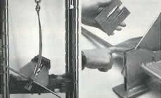
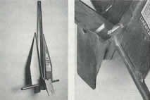
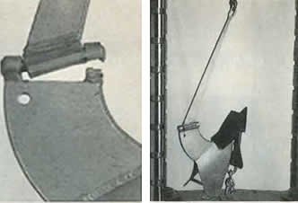
Test Procedure
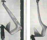
Each anchor was secured shank end up in a hydraulically operated 160,000-lb. capacity, Tinius Olson testing machine. A custom-made, hardened-steel. 3/8" toe fitting was slipped onto the end of the fluke(s) and chained to the hydraulic actuator that applied the load. In order to simulate the type of load that results from the anchor's being lodged in rock, coral, or other hard substance, the load was applied to the fluke ends. In the case of the Danforth anchors, the load was applied to both flukes, since in an actual holding situation, both flukes would likely be wedged in rock. Loads were applied gradually and evenly at a rate of approximately 1,000 lbs. per minute and measured by a load dynamometer.
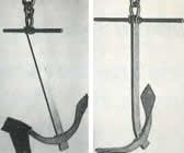
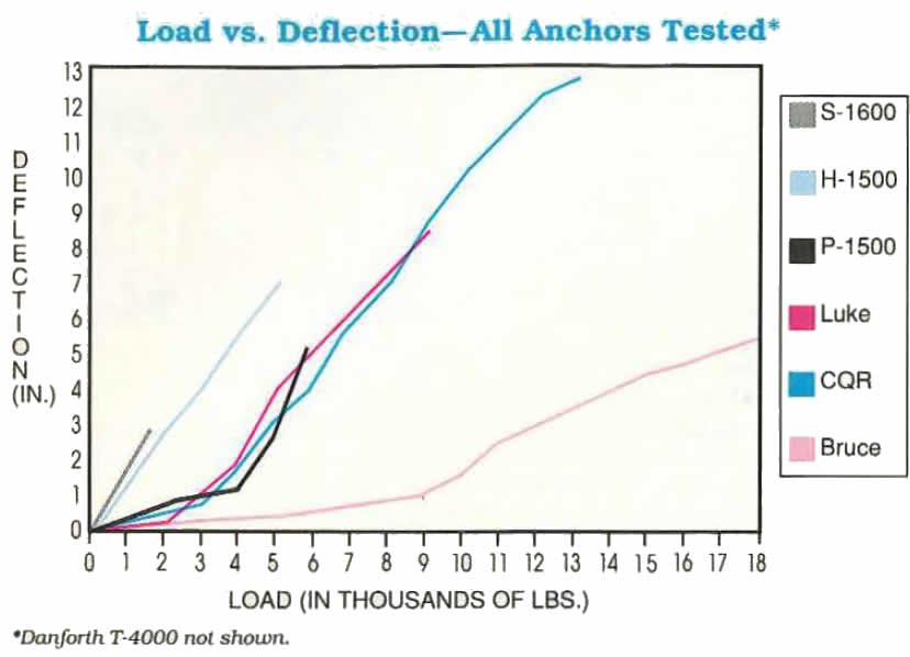
In order to monitor anchor deflection, each ,anchor was secured in the jig, and a measurement was taken from the top of the shank to the tip of the fluke(s) before any load was applied. This distance was remeasured at 1,000-lb. Intervals as the load was steadily increased, which resulted in the deflection curves shown in the graph on page 19. A gradual load was applied until it reached that anchor's rated holding strength. The target load (if known).
At that point, the load was maintained with the shank-to-fluke measurement taken to monitor any distortion. Then the load was steadily increased until either a) the anchor suffered a mechanical component failure, or b) the anchor experienced a 90° deflection from the line of the applied load, rendering the anchor useless. At this point the toe fitting would s lip off and the test was stopped.
Test Results
Danforth S-1600
The anchor failed to reach the target load of 1,600 lbs. At the 1,500-lb. load, the shank pulled through the crown, causing a rollingsheer type of failure of the crown plate. The load was maintained wblle measurements were taken and damage assessed, then the load was reapplied. At a steady 1,500-lb. load, both flukes bent and one fluke tore apart near the point where it was welded to the crown plate. With this structural failure, the toe fitting slipped off the flukes when the shank-to-fluke angle reached 90°.
Danforth T-4000
When loaded to 1,500 lbs., the flexible shank began to deflect. In attempting to reach a target load of 4,000 lbs., the shank of this anchor deflected and twisted as the load increased, then sprang back to shape when unloaded, demonstrating the positive attribute of spring steel. The springy nature of this anchor made it necessary to restrain the stock with nylon line to prevent the flukes from springing out of the toe fitting. For this reason, its distortion could not be plotted in the Anchor Deflection Chart on the next page. At a load of 2,600 pounds, structural failure occurred when the welds holding the crown plate sheared off. Without the crown plate in place, the anchor opened to a full 180°.
Danforth H-1500
Under a target load of 1,500 pounds, the shank-to-fluke angle increased by about 5°. This deflection could not be attributed to any single anchor component. The load was then increased to failure. At 5,250 lbs., the shank strap (which prevents the shank from impinging on the crown plate) failed in tension, then the crown broke. The simple modification at the shank stop in this design gives this anchor a much higher load capacity.
Danforth P-1500
When loaded to 1,500 pounds, the swivel pin connecting the shank to the plow was observed to bend slightly. As the load was increased, this pin continued to bend. When the load exceeded 5,000 pounds, tensile failure occurred when the swivel bushing parted from the plow neck.
Luke "Storm Anchor"
When loaded to 3,000 lbs., the bottom of the steel shank, which passes through an aperture in the fluke arm, began to bend. While the one-piece, cast-iron fluke arm did not distort to any measurable degree throughout the test, the lower portion of the steel shank continued to bend gradually until, at a load of 9,000 pounds, the shank-to-fluke angle reached 90 and the test was stopped.
CQR Plow
When loaded beyond 4,000 pounds, the shank was observed to bend. This bending increased gradually until, when loaded to 6,000 lbs., the shank could be seen bending and twisting slightly. Under a 9,000-lbs. load, the aperture between the jaws of the shank and the neck of the plow widened slightly, probably indicating some bend in the swivel pin. The shank continued to bend and twist increasingly until, at a load of 13,250 lbs., the shank-to-fluke angle reached 90 degrees and the test was stopped. The swivel joint experienced very little distortion.
Bruce Claw
The one-piece Bruce held its shape extremely well throughout the test. While no distortion whatsoever could be visually observed up to a load of 9,000 lbs., shank-to- fluke measurements showed an average movement Before Alter of 1/8" per 1,000 lbs. of applied load, indicating that the load was well spread over the entire anchor. When loaded to 10,000 lbs., the shank began to bend. The load was gradually increased to 18,500 lbs., at which point the shank began to twist slightly as it continued to bend. The test was then stopped briefly to replace a critical piece of test equipment that had elongated. The toe fitting was readjusted and the load reapplied. At a load of 17,000 pounds, the shank-to-toe angle, though less than 90°, allowed the toe fitting to slip off and the test was stopped.
Horizontal Loads on Typical Ground Tackle
| Boat Dimensions* | Horizontal Load on Boat in Pounds | |||
|---|---|---|---|---|
| Length | Beam Power (Sail) | Lunch Hook | Working Anchor | Storm Anchor |
| 10 | 5 (4) | 40 | 160 | 320 |
| 15 | 6 (5) | 60 | 250 | 500 |
| 20 | 8 (7) | 90 | 360 | 720 |
| 25 | 9 (8) | 125 | 490 | 980 |
| 30 | 11 (9) | 175 | 700 | 1,400 |
| 35 | 13 (10) | 225 | 900 | 1,800 |
| 40 | 14 (11) | 300 | 1,200 | 2,400 |
| 50 | 16 (13) | 400 | 1,600 | 3,200 |
| 60 | 18 (15) | 500 | 2,000 | 4,000 |
Comments
It is important to keep in mind that these tensile strength tests are intended to simulate what happens when an anchor that Is hooked or wedged In rock, coral, or other hard substance is overloaded. While holding power is the main function of an anchor, there is no guarantee that the holding ground you choose will be a consistent substratum of sand, mud, clay, or pebble. Often the anchoring bed is strewn with rocks, ledge, coral, or even wreckage. An anchor that Is capable of holding 100 times its weight in sand is of little use if it bends or breaks when subjected to a load of 20 times its weight when a fluke Is wedged in rocks and the wind blows up. While the anchor may not break, its flukes or shank may bend appreciably, rendering the anchor unreliable for future use.
The Danforth T-4000 showed remarkable resilience in the a bility of its shank to spring back to its original shape after twisting wildly. You would expect this anchor's breaking strength to meet or exceed its rated holding power of 4,000 lbs. However, under a maximum load of 2,600 lbs., the crown plate sheared off at the welds, causing the anchor to fail. Among the fluke anchors, the Danforth H-1500 Hi-Tensile showed superior strength, withstanding twice the load of the Deepset before failing. This anchor could be greatly improved with the simple modification of a shank stop, as on the P- 1500.
Of the plow anchors, the Danforth and CQR appear similar in design, but they differ markedly in construction. While the Danforth P-1500's breaking strength far exceeded its rated holding power, in our test it fell far short of the performance of the CQR and Bruce. The Danforth's swivel pin and swivel bushing appear to be the weak link in an otherwise versatile and efficient anchor. When loaded to 5, 700 lbs. (the point at which the Danforth plow failed), the CQR's shank showed some bending and twisting, but the shank-to-fluke angle had Increased by less than 5°. Due to Its drop-forged, high-tensile steel construction, the CQR's shank continued to bend and twist gradually without a tensile failure until it reached a maximum load of 13,250 lbs., more than twice that sustained by the Danforth plow.
The Bruce was clearly the strongest anchor we tested, both in terms of maximum load sustained and its stubborn refusal to bend. Built of one-piece, heat-treated cast steel, there are no joints, welds, or pins to break. Surprisingly, though the load was applied to the central fluke alone, it showed no distortion when the test was stopped. When loaded to 9,000 lbs., the Bruce was the only one in the test group that could still be considered serviceable for further use. And the Bruce is probably the only anchor we tested that would remain hooked in rocks when loaded beyond 14,000 lbs.
To put the results of this test into more meaningful perspective, let's look at the sort of theoretical loads imposed on "typical" boats of various sizes at anchor in a wide range of wind strengths. The table above right, "Horizontal Loads on Typical Ground Tackle," was developed by the American Boat and Yacht Council and assumes freedom of the boat to oscillate, and moderate shelter from large seas. However, surge loading from high seas can double the horizontal load on a boat's ground tackle. (This is where a long rode of suitable strength becomes valuable in absorbing shock loads.) While this table gives only a general approximation of the horizontal loads on your ground tackle, it's wise to keep these figures in mind when choosing your primary working anchor, for use In winds up to 30 knots.
A note about rodes: While Danforth recommends using a nylon rode with a short chain leader for its anchors, Bruce and Simpson-Lawrence (maker of the CQR) specify a minimum of one foot of chain per foot of boat, or three times the water depth, or an all-chain rode. The reasons for this are to add weigh, to increase catenary (the curving, and consequently more horizontal angle of the rode relative to the bottom), and to avoid chafe on rocks. Therefore, most anchor tests conducted in Europe use as much as 75' of chain (about one-quarter of the total rode length), with a scope of between 5:1 and 7: l. This underscores the point that it is not easy to devise an unbiased test.
These are some of the dynamics with which anchor manufacturers grapple when engineering anchors thin enough to penetrate the seabed, broad enough in fluke area to hold under load, and strong enough in design and construction to resist bending and breaking.
While there are many anchors on the market today that meet all the criteria we look for in an anchor to one degree or another, there is no single anchor, nor one style of anchor, that outperforms all others in all conditions.
Further Comments
In Foundation Findings Report #5 (1989 Summer Boating Equipment Reports), we tested the tensile strengths of seven anchors by simulating what would happen to each anchor when its flukes were lodged in rock, coral, a stump, or other unyielding surface in a strong wind or stressful retrieval situation.
Following that report, a number of anchor manufacturers approached us about performing an identical test on seven additional anchors. We put each of these seven anchors through the same paces, using the facilities and technical expertise of an independent testing laboratory, COMTEX Development Corp .. at the University of Lowell, Massachusetts.
The results of the follow-up anchor test are summarized in the chart below. The chart illustrates the strengths of all 14 anchors tested and lists them in order of increasing anchor weight.
No single anchor outperforms all others in all conditions. That's why prudent boat owners stow more than one type aboard. A secondary storm anchor of a different type than your primary anchor is essential safety gear aboard any coastal cruising boat and offshore cruisers should carry a minimum of three anchors.
While holding power is the main function of an anchor, other factors to take into account are: wind and sea conditions in the anchorage, and bottom characteristics (is the seabed hard sand, silt, mud, rock, coral, weeds, or kelp?). Also, the size of your boat, the relative ease of setting and retrieving the anchor; and the stowability.
Tips on Anchor Selection and Use
- Coastal cruising boats should carry a minimum of two anchors and an offshore cruiser should carry a minimum of three. A primary anchor should be capable of holding your boat in winds up to 30 knots and should be well-suited to the bottom conditions where you boat. A storm anchor should be capable of holding your boat In any wind and sea conditions you are likely to encounter.
- In storm conditions, more anchors are lost to rode failure or deck hardware failure than to anchor failure. Be sure all your ground tackle components are adequately strong and free from chafe and corrosion.
- Use only nylon line or a combination of nylon line and chain. Nylon is the strongest synthetic line; it stretches to absorb the sudden shocks of a boat jerking around in rough water, and it resists chafe.
- Unless the anchor manufacturer specifies otherwise, follow this general rule: 3' of chain between the anchor and the rode to hold a 30' boat in most conditions; 6-10' of chain for larger boats.
- When choosing an anchor, know what you are buying. The market Is rife with "budget" anchors and even some counterfeits that resemble name brands. As our tensile strength tests show, construction is all-important. The best anchors represent a significant investment; consider it hull insurance.
- Know your seabed. Check your chart for indications of the type of holding ground. If the water is warm and not too deep, dive over the side to inspect the bottom and see how the anchor is set.
- Perfect your anchoring technique and always be sure your anchor Is well-set before turning in for the night or leaving the boat.